You work hard to make clean parts, and two numbers decide most outcomes: feed and speed. Feed is how fast the tool moves into the work. Speed is how fast the cutting edge travels across the surface. Mix them up and you get chatter, heat, and scrap. Set them right and parts look sharp, tools live longer, and cycles drop. This guide shows you, in plain steps, how to set Feed Rate and Cutting Speed in Machining so your first cut is safe and your next cut is faster.
What Do Feed and Speed Mean in Machining?
Feed is the tool’s advance rate into the work; speed is the cutting edge’s surface velocity across the material. Both interact, so balance them to hit finish, tool life, and time goals. This section defines Feed Rate and Cutting Speed in Machining so you can apply each with confidence.
Where Each Applies And The Right Units
In turning, the work spins; you’ll see feed per revolution (fn) in inches or millimetres per rev and speed as surface feet per minute (SFM) or metres per minute (m/min).
In milling and drilling, the tool spins; feed is inches per minute or mm/min, computed from chip load and flute count. Knowing which component rotates prevents formula mix‑ups. It also keeps your spindle speed (RPM) calculations tied to the right diameter, which is a common source of errors that burn tools or leave lines on the part.
Why Feed and Speed Work Together
Speed drives heat; feed sets chip thickness. Raising speed can smooth a finish but increases temperature and wear. Raising feed thickens chips, which can improve cutting until the edge overloads, then finish degrades. Start from the tool and material data, then tune while watching the chip shape and colour. Strong, consistent chips and a clean edge usually mean the balance is right; dust, bird‑nesting, or blue chips signal a change is needed.
How Do You Calculate Cutting Speed And RPM?
Use cutting speed (SFM or m/min) and the rotating diameter to compute spindle RPM. The diameter in the formula must match the cutting diameter, not the shank.
SFM↔RPM And m/min↔RPM, With Examples
Cutting speed and spindle speed are directly linked. Once you know the desired surface speed (SFM or m/min) and tool diameter, you can find the correct RPM using a simple formula. This keeps the cutting edge moving at the right velocity for your material and tool type.
In imperial: (SFM → RPM)
RPM ≈ (SFM × 12) ÷ (π × diameter in inches)
In metric: (m/min → RPM)
RPM ≈ (1000 × m/min) ÷ (π × diameter in mm)
Example (imperial): 100 SFM on a 1 in end mill → RPM ≈ (100 × 12)/(3.1416 × 1) ≈ 382
Example (metric): 250 m/min on a 10 mm cutter → RPM ≈ (1000 × 250)/(3.1416 × 10) ≈ 7,958
Check your machine’s max RPM and your tool’s balance rating before you run. Slower is safer for a first trial, then step up if the cut is stable.
Classic Pitfalls With Diameter And CSS
Shops often plug the wrong diameter into the equation, like the tool shank instead of the cutting diameter, which skews RPM. On lathes, Constant Surface Speed (CSS) can be active; it raises RPM as the diameter falls. Always set a maximum RPM clamp to protect bearings and avoid overspeed near the centreline. If you see sudden finish changes mid‑pass, confirm whether CSS or fixed RPM is in play.
How Do You Calculate Feed Rate And Chip Load?
Chip load comes from toolmaker data and depends on material, diameter, flute count, and cut type.
fz, fn, and Table Feed In Practice
In milling, fz is the feed per tooth.
Table feed Vf = RPM × number of flutes × fz.
In turning and drilling, the feed per revolution (fn)
Feed (turning/drilling) = RPM × fn
Keep units straight and you’ll keep chip thickness stable. That stops rubbing, which shortens life and ruins the finish. Use your CAM’s chip‑load preview; then verify on the machine’s feed display.
Picking Chip Load By Material And Diameter
Start low for prototypes, small diameters, long stick‑out, or light holders. Then increase until chips look healthy and edges stay bright. Aluminum usually supports higher chip loads than stainless; gummy alloys want sharper edges and good chip evacuation. If chips smudge or string, raise feed slightly or improve coolant and air blast. If the tool sings, reduce radial engagement or feed, and try a different RPM band.
Key Factors for Selecting Speeds and Feeds
Begin with the material and tool grade. Then weigh rigidity, coolant, DOC, flute count, and your finish goals. Together, they set a safe, productive window.
Material, Tool, Coolant, And Rigidity
Harder and work‑hardening metals push you toward lower SFM and moderate chip load. Carbide runs higher SFM than HSS; coatings expand the window. Flood or through‑spindle coolant carries heat away and breaks chips; in some materials, air or MQL is better for visibility and burr control. Rigidity machine, holder, and workholding limits how aggressive you can be. If the setup flexes, lighten engagement and prefer a steady chip over a high-speed number.
DOC, Flutes, And MRR Trade‑offs
More DOC or wider engagement raises cutting forces. To maintain stability, lower SFM or reduce chip load while keeping a clean chip shape. Small‑diameter cutters need lighter chips to avoid snapping. More flutes can increase table feed at the same chip load, but watch chip packing in ductile metals. For thin walls, take lighter radial passes with more axial depth to keep deflection predictable and finish consistent.
Feed and Speed Reference for Beginners
Use conservative ranges for a first cut, then adjust in small steps. Always confirm against your tool’s datasheet and your machine’s limits.
Starter SFM/m/min Ranges And Notes
These beginner ranges are common reference points. They’re not rules. Adjust for tool grade, rigidity, engagement, and coolant. Try a short test cut, measure finish, and check the chips before moving to full depth.
Use this starter table to pick safe, proven values for common materials before fine-tuning on your machine.
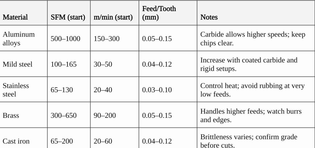
How To Use The Table And Tune Safely
Pick your material row and choose a conservative SFM and chip load. Compute RPM and table feed. Run a short pass and check chips and surface. If chips are thin or dusty, raise the feed a little. If chips are blue or edges go dull fast, reduce speed and improve coolant. Move in small steps; record what changed and how it helped. A simple log speeds up future setups.
When Should You Use Constant Surface Speed (CSS)?
Use CSS to turn when the diameter changes during a pass. It keeps cutting speed near the target, which protects edge life and finish. Always cap the maximum RPM.
How CSS Works And Setting Limits
CSS (often G96) varies spindle RPM to hold your chosen SFM or m/min. Add a safe cap (G50 on many controls) so RPM can’t spike near the centreline. For finishing cuts on profiles and facing, CSS keeps the chip load behaviour more consistent and reduces the chance of rubbing as the diameter falls.
When CSS Helps And When Fixed RPM Wins
CSS shines on changing diameters and long profiles. But if your max‑RPM cap would hit constantly, a fixed RPM may run smoother. On thin or flexible parts, a steady RPM can reduce excitation and help you find a quiet, stable band. Try both approaches and keep notes for each material and geometry family.
Fixing Chatter, Wear, and Finish Issues
Change one variable at a time and watch the result. For heat and fast wear, reduce speed and check coolant. For a rough finish, lower feed or increase speed a little, and improve support. For chatter, adjust engagement and RPM until vibration stops.
Rapid Diagnostics You Can Trust
Loud, wavy walls point to chatter. Shorten stick‑out, reduce radial engagement, and try a different RPM band. Blue chips and crater wear suggest speed is too high or coolant is weak; drop SFM and improve flow. Torn or smeared surfaces in ductile metals often mean chip load is too low; raise feed until chips form cleanly and edges stop rubbing.
Evidence Pack
Keep a small log with material, tool, SFM/RPM, feed, DOC, and photos of chips and edges. Straw‑coloured chips in steel are healthy; black or blue chips show heat. In aluminum, dust or strings usually mean rubbing; sharper tools and a higher feed help. Use the log to build recipes that you can trust for repeat jobs.
Can Xmake Help You Pick Safe Speeds And Feeds?
Yes. Share your material, tool info, and finish targets. They will review your numbers, suggest safe starters, and if needed, run a quick prototype to prove the recipe.
What To Send For A Fast Review
Provide a drawing or CAD, the material grade, tool type/diameter/flutes/coating, target finish and tolerance, and machine limits (max RPM, horsepower). With that, their team can give you a realistic window for RPM, chip load, and DOC that fits your setup and your finish goals. If you want hands‑on help, see Here custom CNC machining service.
From DFM To Production
They can iterate on a prototype, confirm the parameters, and carry the same settings into production with consistent QC. If your part is sensitive to heat or burrs, they will suggest tool and coolant adjustments that keep geometry true and surfaces clean.
Final Verdict
When you set Feed Rate and Cutting Speed in Machining with intent, you protect the edge, hit finish, and cut cycle time. Remember the simple math: compute RPM from SFM or m/min and cutting diameter; then compute feed from RPM × flutes × chip load. Adjust for material, tool, rigidity, coolant, DOC, and your finish targets. Start with conservative numbers, check chips and edge wear, and tune one step at a time. If you want a second set of eyes or a quick prototype to de‑risk a new material, Xmake is ready to help.
FAQ
What’s the quickest way to find a safe RPM?
Use the toolmaker’s SFM, convert to RPM with the actual cutting diameter, and confirm the machine’s max RPM. Start low, take a short pass, then step up.
How do I choose the chip load for a small end mill?
Stay near the low end of your tool’s range. Small cutters can’t carry thick chips. Increase feed only as long as the cut stays quiet and chips look healthy.
Is higher speed or higher feed better for finish?
Often, a slight speed bump with a small feed drop improves finish, but heat rises. Watch tool wear and coolant performance while you tune.
When should I avoid CSS on a lathe?
If the max‑RPM cap would be hit constantly, a fixed RPM can run smoother, especially on flexible parts or when the spindle speed band excites chatter.
Do starter tables replace the tool’s datasheet?
No. Tables are only starting points. Always check the exact tool and material data from your vendor and adjust for your setup.
Experienced SEO Specialist and Web Developer with a strong focus on off-page SEO and guest posting. With 3 years of proven expertise, I help businesses improve their search rankings and build sustainable online presence.